A “truss” is what you see when you look at a truss bridge from one of its sides. A truss is typically made up of a lot of triangles, but some uncommon truss designs don’t have any. The purpose of a truss is to help a bridge support a load (car, train, person) from any point along the span of the bridge. Without a truss, you simply have a beam bridge.
Overview of Terms
Let’s define a couple terms to help you understand how to study truss design.
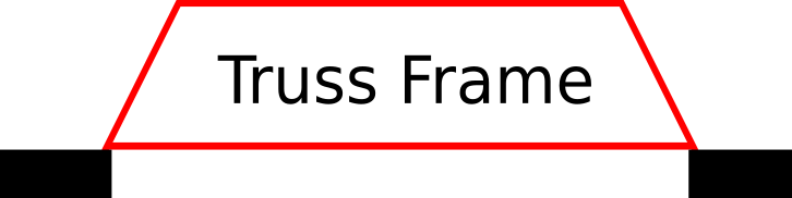
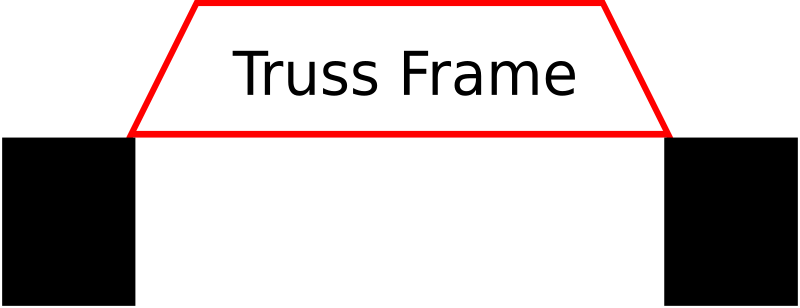
Shown here in red is the Truss Frame. The frame is the outermost parts of the truss.
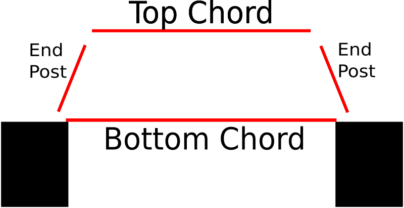
The frame is made up of several parts: Top chord, bottom chord, and two end posts. This diagram shows the frame in an expanded view so you can easily see each part. Practically, you might use different sizes or shapes of wood for each of these parts due to the force being put on each part is different.
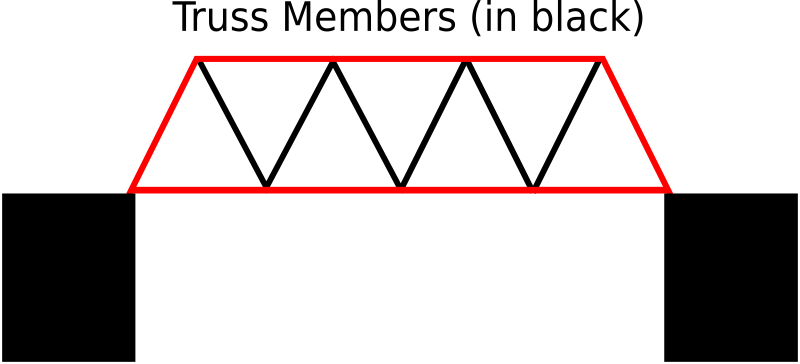
Now we will add the truss members, which are shown in black in this diagram. The truss members are simply an arrangement of triangles (most of the time) that transfer the force/s put on the bridge to the ground. The way these triangles are arranged or shaped is the essence of truss design. You will see examples of the most common designs further on this page.
These terms will be helpful to keep in mind as we talk more about truss design. Now let’s take a quick look at the history of truss design, particularly in the United States.
Brief History of Truss Design
While trusses have been used for both roofs and bridges for many centuries, there was an explosion of truss advancement in the 19th century in America. The need for bridges to span longer distances in this era, as well as to hold increasingly heavy loads, brought about many creative solutions in the form of new truss designs.
Three names stand out as true pioneers in these early truss bridges: Timothy Palmer (1751-1821), Louis Wernwag (1770-1843), and Theodore Burr (1771-1822). These men, along with other bridge builders who followed them, designed and built many bridges, especially in New England. Theodore Burr came up with a design that was used in many iconic covered bridges, and some are still standing today. These men came up with practical solutions for bridge building, and did not know or have access to the theory behind their designs.
Interestingly, building bridges in the 18th and early 19th century was more about quality of construction. Skilled carpenters were needed, and most of the engineering was practical and not theoretical. Wood was the primary material available in these early years, but iron and then steel came along and changed everything.
With iron and steel, and the expansion of railroads that carried heavier and heavier loads, new bridge designs were needed. The Howe and Pratt trusses in particular were designed to incorporate iron rods in the truss. These two designs, which you can see from the original patent images, do not look exactly like the truss designs that we associate with those names today. This is a bit of a mystery to me, but you can see semblances of the original designs in the modern depictions. Both the Pratt and Howe patents were very much concerned about methodology of construction more so than the actual design.
Bridge history is fascinating, and there is so much more to learn. This short section is meant to whet your appetite, but now we turn to the application of truss design to model bridge building.
Common trusses used in model bridge building
Each of the following truss designs are very common in both real and model bridges because of their sound engineering and ease of construction. As I mentioned earlier, the key for us model builders is how these designs transfer forces throughout the bridge and eventually to the bridge supports. Each of these designs does that in a different way.
Take some time to read up on each of these designs before deciding on one to use for your bridge. Perhaps you will end up not using any of these designs but creating something on your own based on the principles of force transfer.
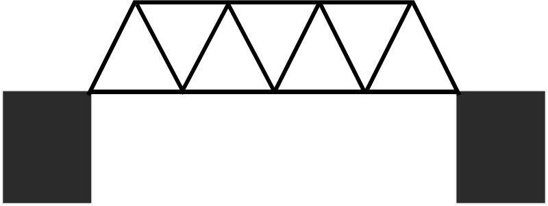
Warren Truss
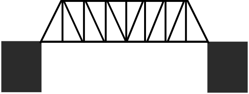
Pratt Truss
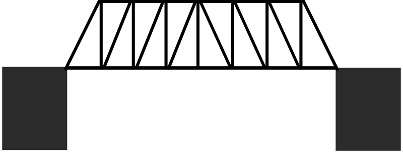
Howe Truss
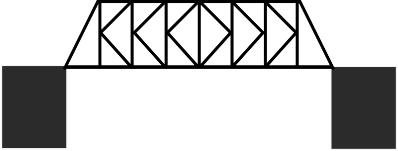
K Truss
I have chosen to highlight these four examples of different trusses to get you started with some very solid examples that you can easily use on your bridge. There are other, more complex, designs that aren’t shown here. You can do a web search for truss design and see many more examples. I’m a fan of keeping things simple, but it is possible that your unique bridge project would benefit from one of the more exotic designs.
If you are interested in learning more about trusses and truss design, check out Truss Fun, Second Edition from Amazon. This is a comprehensive study on the engineering principles behind the design of bridges. It is easy to understand and to follow, and is a great fit for students who are just learning, but advanced enough to be a great resource to those with more experience.
This is a great site. Thank you for taking the time to put it together.
are you 11? what do you think would happen if you reversed the k’s? your bridge would only be as strong as your adhesive since all the weight would pull on the supports rather than sit on them… you’d increase the stress on joints considerably!
and what would be the purpose of removing the verticle piece? and those green verticles… sort of necessary to hold up the supports. what’s the point in even having that first support? physics… seriously.
You asked a really good question about the “green” supports. The program shows that they have no load, so why even include them on a bridge?
The reason is that the truss design program is dealing with theory only. However, in a real model bridge scenario, the bridge is going to twist and deform under load. Once the bridge starts to deform, then the forces go wacko. The green members might suddenly go red or blue. By leaving the green members in the design, you are putting a small safety factor into the bridge.
It would be an interesting experiment, however, to see if you can achieve a greater efficiency by leaving the green members out. The bridge might not hold as much, but because it will be lighter it could potentially have a greater efficiency.
The other point with the green members is the location of the load vectors. They are shown in the ‘dead load’ mode; when the ‘live load’ configuration is considered, there are no green members.
this website is very usefull even though it did not answer all of my questions on model bridges. With that said this site is still the best one that I know of that has good information on how to make model bridges and the materials and tips to make it a good one!!!
Arianna, what questions do you still have that I could answer?
Hey it’s me againthank you very much for the advice i am going to try the welbonde again but it turns out the bridge i am building has to have an opening so “boats” can pass not cars and i was wondering if i put a k-truss on arches would the bridge be strong or is their a different type of method to building those types of bridges
thank you again this website is easy to use for all ages
My first question is how can a beginner understand everything about bridges enough so to make a bridge under 16 grams and withstand a lot of weight????
Arianna you have to build a bridge too 16 grams or less? weird i have to make on for school
First Timer, a K truss is a good choice. As long as your construction is done well, it should be a good bridge. However, I am not sure what you mean by your bridge has to be on one plain. Could you explain that for me?
of course by on one plain it means we can not place pieces over the joints to help stability it has to be flat basically but you said a k truss would be good for an arch bridge?
I think I understand now. Yes, a K truss is a solid way to build a bridge, just really work hard on getting your joints perfect.
Im building a bridge out of popsicle sticks and im using the truss design. Im not sure which type of truss is stronger because i will be putting bricks on it to test. I was going to do the Warren truss but the way i built it so far makes the triangle on it not equilateral. I was then thinking about a Howe truss…..What is your opinion?
thanks so much man your a genius
It does not matter very much if your triangles are not equilateral. The triangle is a very strong shape period.
i’m using a pratt truss what will happen if i add an extra line going straight through the middle and add X’s on top and at the beginning and end.
thank you so much i think i’m going to ace this assignment
Manuel, are you talking about adding a horizontal line in the middle of the Pratt truss? Don’t do it. Try plugging that design into the Bridge Designer program and see what happens. It is basically adding useless weight.
I am not sure what you mean with the X’s at the beginning and end. Are you talking about lateral bracing?
Garret Boon, yes I am talking about lateral bracing. I didnt know what is was called
How do you determine the optimal width of a model bridge? We have to make an elevated wooden bridge that has a span of 45 cm, a tower height of 7 cm and a maximum height of 15 cm (including the tower). Pls advise. Thanks.
It sounds like you are in Science Olympiad. If so, then you don’t want the bridge to be any wider than it has to. The bridge should be just wide enough to accommodate the loading block.
Also Garret do you know any one else that i could contact for another interview we are required to have 2 and yours was great and because your so reliable and intelligent anyone that you suggest has to aswell
FT, model bridge geeks are hard to come by :P. I am not sure of anyone offhand who you could also interview. The only thing that comes to mind is a forum where you might could find somebody. http://www.scioly.org/phpBB3 That forum has a lot of model builders.
John, good question. Nothing changes about the truss in an arch form. Whatever piece was in tension before will still be in tension on the arch bridge.
i have an assignment and it is graded upon how close i can predict the breaking load for the bridge. I cant do 2d trusses using method of joints and sections.The tensile and compressive forces change on adding the lateral bracing. I was wondering if you could point me in the right direction to sole 3d truss systems
Thanks GB!!!
In theory can these designs and calulations be used to design and calculate for roofs? I am studying truss roofs and found your web site. Thank you Dan
Daniel, in theory yes. However, they are issues that apply to a roof that don’t apply to model bridges. This website was not meant to provide engineering information about real life scenarios.
these bridges are awsome they give me lots of ideas of how to build a bridge…… thanj you for your help
thank you soo much I have been looking at different disigns for a truss bridge im a 8th grade student and Im mix some of the ideas that I’ve seen. I’ve tried to combined the basic ideas of warren, pratt, and howe. I’ve tried pratt and howe. I will also look at the K-truss and see the strengths i think would work best of it because it is a truely unquie disgin that i am glad I’ve found on this web site.
hey i am building a bridge out of popsickle sticks and i can only use 50 of them and it can only be 5 inches high and 4 inches wide
could you tell me the best truss design to use?
thanks man!!!!
All you fellas:
Do some research yourself mate. Don’t just wait around for someone to reply to a post. I have got a similar project and have realised that you have to do some work! Answers dont just come without a price!
[edited by admin due to comment policy]
David if i were you i would check the popsicle bridge area if the website it has kits to help you make popsicle stick bridges.
Also Peter i agree these fellas should do some reasearch for themselves but the thing is this is the best website to do it at there a myriads of links and resources about almost every aspect of bridge building design etc. ‘
Also we apologize for any question that we were not able to answer we will try our best to do so.
there is mistake in calculating the forces in members of first warren truss,check it
I have double checked the first example and it seems fine to me. You have to remember that changing the dimensions of a bridge will affect its load distribution.
I tried to build using the Bridge Designer, the first example of calculation used in the TRUSS DESIGN page (” On this Warren truss, each of the down arrows represents 50% of the load….). It does not calculate the load distribution:” No solution. Matrix is singular.” If I want to add memebers or nodes the formula relation” member+3=twice the Nodes” is not satisfied. What should I do to get your result?
I can’t really know what went wrong without seeing what you did. Just make sure that you don’t accidentally add an extra node somewhere.
It seems to me there is a calculation mistake in the howe truss.
If there is no other load how could be the 10 the value of the tension in the first member of the bottom chord, when the top chords first member is compressed by 15?
i analized the first two warren a bit, and something is not good about the first one.
(I checked them with your bridge calculator and manually too.)
Hey, just want to know if you sell plans just for Pratt,Howe,and Warren truss bridges. I really need those for a project.
Thanks a LOT :()>
Jacob, what materials are you building your bridges out of?
Your website is really really helpful. I don’t know what I would’ve done without it. I had a question about the trusses. Which truss would be best for a bridge that is elevated by two pole things at each end? I need to have a good efficieny score, so I need to use a truss that won’t weigh much, but hold a decent amount of weight. Once again, thank you so much for making this site.
Double A,
I suggest using the warren truss as it is the most simple to build and can hold a descent amount of weight. Also using vertical members in the warren truss is another good option. So far that is what I have been using. I assume you are doing the elevated bridge event?
Double A I have made many bridges and one of my most recent is a cross of a howe and pratt. It is a it harder but has a much higher efficiency
“The following figures are shown under a load. The numbers represent percentage, where the total load = 100. The numbers are rounded to the nearest 5. For absolute numbers, visit the Bridge Designer.”
I do not understand what this means. Could someone please explain?
Also, what is the difference between compression and tension. I understand that tension is like stretching a spring and compression is pushing the two ends together but I dont understand how this relates to bridges. For example: If a truck is driving on a bridge, is it applying tension or compression on the bridge?
Thank You,
Petey
The total load on the bridge = 100. The loading point is indicated by an arrow. This could mean 100 pounds, or 100% of some unknown load. The figures show how the load is spread throughout the truss with a number. Look at the first color figure, the warren truss. The top piece is in three sections, and each has a number. This number shows the load that is on that section, which is 50 on the outside and 85 in the middle.
The different colors show the difference between tension and compression. Imagine there is a truck in the middle of each bridge on this page. Any piece that is red is in tension. Any piece that is blue is in compression.
I understand the point about compression and tension, but I am still not understanding the load.
If there is 50 on the outsides and 85 on the insides wouldn’t that equal over 100?
I am still confused about that.
Basically, the numbers on the top would represent how much of the load is distributed to this point on the bridge. The 85 would, if im correct, mean that this is the point on the bridge that is under the most stress. 50 would mean that this area is under less stress than the middle area of the bridge. Hope i made sense and that this helped you.
I have to build a bridge out of spaghetti and glue for a school project. I was wondering which bridge design you would recommend so that my bridge could hold as much weight and possible (the weight is being suspended from the bridge in a bucket and is attached to a piece of wood that will sit on my bridge)
Well, i think what you need to do is see which truss design distrubutes the weight most evenly. The more distribution of weight you have the better your bridge would hold up. From what i see it looks like the k truss bridge distributes the weight most evenly. I made a bridge out of popsicle sticks that held over 200 lbs. I used the warren truss bridge but the k truss seems to distribute the wieght more evenly.
so which one would hold the most weight??
that question can really not be answered. there are alot of determinig factors. 1)how the weight is applied. 2)what materials you use. 3)how much materials you have to work with. etc.
I want to build one project under civil department. its a competition..
I have to build a truss structure using Popsicle. But it will not be tested with vertical load but with horizontal force. Actually judges will attach a string on the top of my Popsicle truss structure which will go over a pulley and will carry a load at the end of the string..
Could anyone plz suggest what structure will be the Best for this very purpose! I need help as soon as possible.. Thnx.
I personally made a warren truss bridge out of popsicle sticks and wood glue. It held over 200 lbs. i cant say that this is the best design to use though. You just need to find which design distributes the wieght most evenly. But i didnt exactly understand how you said the weight would be applied.
i made a truss bridge that was 40 cm long. i used the warren truss design. i added vertical suports also though. it was made from popsicle sticks and wood glue. the key is distrubuting the weight evenly. my bridge held over 200 lbs. depending on the materials and how much you have to work with, you should be able to do the same.
Also a determining factor would be exaxtly how the weight is going to be applied to your bridge. i also forgot to mention that my bridge was 10cm wide.
200 pds wow if u want us to believe u say something reasonable 40X10 cant hold 200 pds it would have to be 50 cm high considering u used normal wood glue.
Sorry, but yeah it could certainly hold 200 lbs. He most likely beefed it up with a lot of popsicle sticks. Wood glue is good enough if used properly. I saw a vid on youtube with a simple king post that held so much, they were running out of things to use as weight. It was REALLY strong.
hey josh im tiana and im in yr 7 and we are making bridges and how do you know if it is the write bridge and there is other choices what do you do ??????
When you stated that for a Howe Truss you would have to use larger compression members, were you referring to the diagonal members or vertical members? Thank you for your clarification.
i have to biuld a bridge for science fair do you think that popcile sticks would be the way to go , but i also need the bridge to break at some time with in 5-10 minutes. anyone can answer to this i just need some kind of answer. 🙂
i would also like it if you just posted here on the website!!
please someone respond soon!:D
thank you
p.s. i think that this website could use some more information on the different kinds of bridges and not just on your experiments you should have a viriety of appinions so that people will see two or more sides of the story!! OKAY? DO NOT take this as a insult i just think that it would be better that way , i thnk it would guve you more viewers than what you have now !! just my apinoin but i bet other people agree with me on this matter!! *****
sorry if that sounded wierd :D/:( !!!!
Rose, part of the reason I have the option to leave comments is so people can share their opinions about my bridges or projects they have worked on. I also have an option for people to upload photos of their own bridges, so this site is not just my own work.
Any bridge can break within 5-10 minutes. It depends on how strong it is and how fast you load the bridge.
Yeah I’m doing the same thing but we have to use toothpicks which is so much hard so yeah if any of you have advice I would like to hear it but it will be hard!
For a science fair i have recently done, i had the warren, pratt and howe trusses all trusses.
the efficiencies in weight held over bridge weight were:
warren – 385.6 reoccurring
pratt – 425
howe – 340
These are not averages of several bridges, and they were only 1 foot long (cause thats what the stores had in stock.)
In this test, they were weighed by hooking a rope to the bottom beam, putting a bucket on the rope, and adding coins to the bucket (and a ten-pound weight).
I hope this answers some questions on which is best (the pratt)
Of course i had 30 pounds of coins.
Thanks, very much for that insight Liam. It was very helpful and I am very appreciative.
p.s. thanks for the info, this is very helpful
Hey Liam are you in the Snowshoe Ski Team????
If you read this I will be soooo happy please reply!!!???? 🙂
Has anyone else noticed that the K Truss looks like it has arrows in it as well as Ks? Its like an optical illusion! Great Website, and thanks for the tips!
oh yeah, i just noticed that. That’s really cool.
. It is the simplest design of the Truss Bridge, with two sides, a bottom, and the railing in simple triangle forms. The bottom of the side of the bridge is 11 inches in length and the top of the side is 10 inches in length. The little rails on the inside of the left and right side of the bridge are 2 inches in length. The bottom of the bridge…… Some of the things I learned in making this bridge were the different jobs involved in the process of actually building a real bridge. You need to have an engineer, an architect, a scientist, and a mathematic. You would need an engineer to help design the bridge. You would need an architect to oversee the construction of the bridge. Also, the architect would prepare information on the structure’s design and specifications, materials and equipment, estimated costs, safety, and construction time. They also make scale drawings and make sure that the bridge meets the building codes and laws. Also, to build a real life bridge, you would need a mathematic. They would make sure that all the little details in the bridge were exact and specific so the bridge was safe, and also look right.
hi, im in yr 12 and im currently doing an assignment on bridges
ive built the warren truss bridge with vertical members,
ive had a look at your diagram with the load factors, but im quite confused, you say that the load factors add up to 100% but i dont see how the numbers come together to make 100%
i can only see that when 85% + 15% = 100% at the bottom line, but with the 60% lines i cant figure out how they would add up to give 100% please explain to me =]
Actually, he meant to say that the two black arrows above the bridge represent a single weight, distributed evenly between those two arrows (thus, 2 points at 50% each = 100%), the numbers on the bridge lines are the force amounts(not percentage) most likely, in Newtons. Hope that helps explain things better. There are many free online bridge building games for you to try your own designs and see how they work. I tried a K-truss design in one program from West Point, but the forces were completely reversed. It might have been the program’s physics, but I’m not sure. I had lots of compression at the top and tension at the bottom.
this is a good webstie for teens and it gives the motives for kids to learn how to build bridges.
is this Mrs. Goodfellow from CMS???
Why yes, I am from CMS.
I love this site…it gave me a lot of help for our project. Thanks soo much. I just hope that the bridge that my group makes wins. Um, our bridge is meant to be 40 cm long and we have 150 paddle popsticks to complete it. Anyway, thanks a lot again.
The school I got to St.Peters grade 6s had to build a bridge for Design+Technology and this website has really helped alot thank you!!!
thanks for the tips. i have to make a balsa wood bridge that will support 15 kilos in the center and the truss designs really helped.
trying to redo the bridge
–____________
, /– /— /– /
/__/__./__/__
PRESSURE AT THE DOT
THX, hope it came out
i’m so silly, this is a U.S. site, all the same, i am in AU, so if you can, is it possible to rely to me in metric units? i don’t really know how to convert it. But if you can’t either, I will use a google converter
please reply 2 me, i need help!!!
Nicholas, the force distribution is the same if the load is on the top or on the bottom of the bridge.
even though i agree with you, it is the problem of compression VS tension that i am up against.
nicolas is correct.
so, what bridge would you recommend that will make me win the bridge building contest of 2015?
Hi I have to make a bridge out of straws and masking tape that spans one meter in between two desks plus it has to hold two 5cm cubes full of sand which i calculated and can be no more than 20grams. The most efficient bridge able to hold this weight wins (least amount of straws). Any suggestions on what type of design i should use?
I have the same problem. Can SOMEONE please help us?
Where must the cubes be located in the span?
In the x and y axis located in the centerfold of the main bridge compartment, DUH!
im doing a similar project, but with hot glue and popsicle sticks and im having trouble deciding a truss type. it need to support 50 lbs of weight,be at least 18″ long, 4″ wide, and a max of 12″ high. any ideas
I just built a Warren Vertical Support Truss Bridge out of toothpicks and regular white Elmers glue tha supported 121.7 pounds of sand. This design is typically made for railroad bridges because of the extreme amount of weight a train weighs fully loaded. Good luck.
Try using the london crossover?
one thing you should do to make the joints stronger is cut vertically up the straw and stick it in the end of the other straw and just use a little take to make sure it stays.
im making a warren for my elective with balsa wood.
what would be better a subdivided warren type or a warren with vertical supports?
I do not know what you mean by a subdivided Warren truss. What does this look like?
The vertical supports on the Warren truss allow the bridge to sustain more weight. =) <3
would that be like the pratt truss?
Reference the zero force members. In real life, the loads on bridges are applied at the panel points, so those members would carry a load, even if just a panel load.
You would make member identification much easier if you were to use Bowe’s Notation. With the external forces shown in place, number all the spaces between the forces. From left to right, label the interior spaces with alpha characters, starting with A. Each force can then be identified by thespace number before and after; each member can be identified either by a number-alpha or an alpha-alpha designation.
Thank you for your comment. Could you explain more about panel load?
I will look up Bowe’s notation. Do you know offhand where I might find an example (a picture) of it?
Thanks.
The panel points are the points where the load is applied, usually the joints on the top and bottom chords. For a bridge, beams, carrying the roadway or railroad, would span between two trusses and apply their loads to those points. For a roof truss, the purlins land at the top chord joints.
I found a site for you that shows Bow’s Notation, slightly different than I described because he needed to number the joints for the graphical solution that he describes. The graphical analysis is very accurate, before computers and calculators came on the scene, I used to check my calculated results that way.
http://wjesus.org/Frame_3.htm
Hello!!! im at school trying to win the bridge building competition !!! you guys really helped me!!!!
thx thx thx!!!
your Falaviena
I won a competition at my school too! i wouold like to thank My mom, Garrett Boon, and Michael Jackson for support!
I think the pratt truss is better.
someone told me that the compressional members are more efficient if in an I shape or in a T shape. . .
hey, love ur work! love ur song! which is the strongest bridge design? i’m a big fan of ur designs,
i recently made a k-truss brigde in tech-ed class that held over 350 pounds i used hot glue and wood glue and about 100 or so popsicle sticks it was pretty cool because once it broke i didnt just falter ubder the wait it exploded!
Hey Jake,
How did you make the K for the K truss using the wood? HOw did you make the < stay on the | ? Get what I mean? Please reply quick!
I think that the strongest one is the Howe. Mine held 150 pounds when it was mad of very thin wood. anyone need help? ask me… Skipper
hey can u help me with a project? I think it has to be a specific size but it has to hold more than 150 pounds. help me. please.
I reccomend the howe if u are using stronger wood than mine. mine was thiner and smaller than popcicle stix.
hello i am doing a bridge building contest in illinois at my school, Fenwick High School. The bridge must be able to hold 50 kg if i am to have any chance at winning this contest. What design would you recommend?
Luke, this is the type of question that I just cannot answer. You have to consider what materials you can use, the span of the bridge, and how dedicated you are to winning and learning what it will take to win. The Pratt, Howe, and Warren trusses are great designs. They have been used for real bridges for over 150 years. Choose any of them. But it is not so much what design you pick, but rather how you build it. The care you take in selecting your materials, and the effort you put into the construction are key aspects to the performance of your bridge, just as much so as the actual design.
Garrett, I have a project in which I have to build a truss bridge with pre-cut wood. They are the really thin but long ones made from basswood. The way the weight is applied is by placing a block inside the structure with a pipe from the bottom to pump more pressure. How would you suggest I build the “floor” of the bridge to support the weight?
Thanks
Caleb, my first recommendation is that you make your bridge just wide enough for the block to rest inside. The block should rest directly on the two bottom chords for maximum strength.
which of these designs are best when the weight is loaed by hanging the weights from the botton of the sturcture??
Maggie, it doesn’t matter.
okay, thank you
Hi, I am doing an extra credit project for my school and I’m am suppose to construct a bridge out of craft sticks and glue. I have been researching for different bridge structures I could try, but I would like to know your opinion in which structures I should try first. Also, this bridge must be able to hold a text book that is about 3kg, this has been a obstacle for my bridge. I would greatly appreciate your input.
May, check out my popsicle bridge photos:
https://www.garrettsbridges.com/category/popsicle-bridges
That will help give you some ideas of where to start.
Hello! Our team is making a bridge out of basswood and when we test our bridge, weights will be placed on the bottom floor center. We were going for the Pratt or Howe design but we got confused as to which one is going to be able to support the centered weight the most…or does it not matter?
Thank you!
Doesn’t matter.
Hey, Garrett. I’m building my first bridge (out of basswood). My design’s really simple; I’m doing a Warren truss with vertical sticks in between the sides of each triangle.
My question is this: I’m gluing the sides of each triangle to the outside of the bridge. Would it be better to glue the vertical sticks to the inside of the bridge, or on the outside as well?
Thanks.
This is a great question. The answer, according to my knowledge, is slightly complicated. When you take a stick of wood and hold it vertically with one end on a table and the other end in the middle of the palm of your hand, you can push straight down on the stick. Because the ends of the stick are “free”, the stick bends in a perfect arc shape. However, if you were to push down while holding the ends of the stick, it would bend in a more complex shape. Perhaps an S shape or something weird. In the second case it would be harder for the stick to begin bending. Thus, by holding the ends of the stick you actually increase it’s strength.
However, if you glue a piece in compression on the outside as you say (called a Lap joint), the strength of the joint is in the surface face of the wood. And End joint (see my Bridge Joints page for pictures) doesn’t have that issue. The ultimate joint for a member in compression is a Gusseted joint. It combines the value of End and Lap joints. However, it uses more wood and glue, and thus is heavier.
If I’m building a warren truss (basswood), does adding verticals in the triangles make much of a difference in the weight it could hold, or is it just adding unneeded weight to the bridge?
Sarah, the verticals in a Warren truss are quite useful, and can add a lot of strength to your bridge. They break the top (and bottom) chord into smaller sections. This helps because the top chord is in compression. Wood will bend and eventually break (buckle) when under compression. The vertical members help the top chord resist buckling and thus increase the strength of the bridge. Great question.
i am building a warren truss with vertical supports, made of popsicle sticks, and wood glue. is this good enough to hold 20 lbs.??
Most likely, depending on how well you construct it.
Yes, definitely. I built one and it held 34 pounds
I know that this page is devoted to Trusses, but what are the advantages/disadvantages of using an Arch as opposed to a truss?
The bridge must span 20″ and have a maximum hight of 10″, performance is based on weight ratio, however I would love to break the school record. Made of 1/8 x 1/8 x 36″ balsa stringers.
thanks
What truss design do you recommend if there are 5 equal loads placed across the top of the bridge, if the bridge span is 10 inches?
I was thinking that the warren truss design might be best and that I should double up the thickness of the trusses inside the span. But this is my first time trying this so I don’t know.
Hello I’m in 6th grade and I am seeing which design of truss bridge is the strongest. I am doing all of the bridges above, but I was wondering which materials would be the best to use… Please don’t say metal or something expensive because im only in 6th grade. Thanks!
Zoe, you might want to consider checking my popsicle stick bridge plans for the different types of trusses. You can look at them here: https://www.garrettsbridges.com/store
please help me! it is extremely urgent! i have a blue print due soon and i really need to know how the floor of mt warren bridge should be to make it more supportive! the bridge has to hold at least 1 to 5 kg handing from below it in a cup hanging on ropes from the bridge. i really need fast help, thanks
Probably dont need to support the floor, all the wieght will be on the sides(because of the ropes).
I made a bridge that was 496g and 70cm long. It was a combination of a howe and pratt truss(they made Xs like lXlXlXl) with a supporting truss below the stress point(where the ropes will be).
it hold 200pounds, but we didnt have enough weights to continue, it didnt crack or have any damage on it(other than divets where the ropes rested on).
You shouldnt have any problem with holding 1 to 5 kgs.
Austin, I do not understand what you are asking.
he means like an s and p in the frame of the bridge or so you cand see the shape of his intials
the best way is to put a stick on a stick to make an X figure
They aren’t equilateral triangles that warren trusses use, They’re isosceles triangles. Equilateral triangles have the length for all three sides, which are not what were used for the example image. I’m not saying they can’t be equilateral, it’s just you make it seem that they can only be made up of equilateral triangles
Alex, good point. I made a mistake with those example images for the Warren Truss. A true Warren is indeed made from equilateral triangles. I have updated the images in the article. Thanks.
Which triangle is the best? equilateral or isoceles? and out of these 4 which bridge is the best?
Equaliteral because you want it to be sturdy and strong and in a right angle to hold more efficant, and im an 8th grader.
You can’t have an equilateral triangle that is right…
i agree with Jerome.
Well for it to be a right triangle it must be scalene so but an equilateral triangle would work the best.
No, a right triangle can also be an isosceles triangle with two 45º angles and one 90º angle. Equilateral triangles are ideal because they evenly distribute the force among all angles. These work well for trusses, but for your tension and compression beams, it is best to combine them in a right triangle so that you can put more weight on either the tension of compression beams (depending on the tensile and compressive strength of your material).
Equilateral is always the best. The pressure hits the same on all sides. Good luck!
thanks for the help(: i got an A woop woop <3
actually the pratt and how truss is the best
Dear Mr. Boon,
I am an eleventh grade student and I would like to take this time to thank you for your wonderfully helpful website. My physics class is currently beginning a balsa wood bridge project and your examples of different trusses have been particularly helpful, as well as your tips on types of glue and types of joints. I would also like to take this time to ask a question. For our bridge, we are being given strips of balsa wood that are about a centimeter cubed. Would doubling up the wood be helpful and more supportive to the overall structure, or would it simply make the bridge weigh more and subtract from the bridge’s efficiency? Thank you very much for your time and consideration.
This is a very simple design but works very well and is super strong
Hi, I’m in Year 12 and we need to design a lightweight spaghetti bridge and I’m currently deciding between Warren truss and Howe truss. My teacher in Engineering told us that we should consider pasta stronger in compression than in tension and from what I’ve “researched”, the Warren truss is the best but the Howe truss is good in compression. I’m not sure which one as I’m not sure whether warren is better in compression. Please help me decide.
how do u calculate the ratio of the weight a bridge can hold?
The easiest way is to load it till it breaks, and divide that weight by 5 or so. Don’t trust it with lives, but you can bs an estimated max weight. To do it right, you need to perform a static analysis of the truss members (look up the joint method on google) to determine the load on each member. Then you need to find the shear and bending moments of each of the members (or so I think, I’m in mechanical engineering, there might be an easier way, probably not, still google that). Find all these values as equations with a weight variable in them (i.e. force on the member ab = 2.1*W). Then you can determine when your welds (whatever holds your members together) will break by googling the welds rated forces (compression, shear, tension) and setting the highest weight ratio equal to the max values then solve for the weight (your max weight before the first weld will likely pop). After, you set the largest bending moment in the bridge equal to the largest recommended bending moment of that material. Reference a material guide, steel beams are by convention rated to a max bending moment which can be found via google, wood can be found too for simple shapes, straws and hollow pipe must be researched on how to calculate it. This determines the highest weight at which the member most susceptible to bending is going to buckle. At last you can check the maximum tension and compression of the materials against your highest member tension and compression in the same way, using the reference probably found in your last google search. The lowest of those weights will shows you what weight the first part of your bridge to fail. Divide that value by 5 for a factor of safety and you’re done, that’s the max rating for your bridge.
Hi I’m in year 7 and we are doing a truss bridge assignment and I can’t seem to figure out what a comparative ratio or the total load carried for the research assignment and you seem to know a lot about trusses
I’m in 4th grade and there is this thing where my table group has to do a bridge making contest where we use 100 popsicle sticks to make a bridge. Also, I really like the desines for the bridges. It’s amazing.
I think it’s funny because I am a freshman in high school and we have to do this for a honors geometry class. I wish that our school district was more interactive with engineering designs
Even funnier; I’m a sophomore in college for mechanical engineering and we just made popsicle stick trusses in our statics class to see who’s design could hold the most weight. Pro tip: I’m a personal fan of the Warren truss (as long as your weight isn’t at a specific point, but is distributed across the whole bridge).
I am in the seventh grade and the warren worked quite well with toothpicks. It will probably hold 50 pounds but i had support underneath.
good website, helped me and my friend justin in my POE class in school.
Thanks to this sight my friend Sam, and I are going to have to build a project. More or less a spaghetti bridge
I’m in 8th grade and we have to make a bridge with spaghetti so this helps a lot. Lol
Whaaaaaat?! At least we get actual wood to work with! I feel so bad for you
how do you make a bridge out of spaghetti?!?!
I’m a sophomore mechanical engineering student at Boston University. In my mechanics course we’re analyzing bridge trusses made of straws. Great info on the merits of the different designs.
This really helped me and will be good for my project.
That’s interesting that the need for bridges in the 19th century of America brought about an explosion of truss advancement. I am looking at getting some building trusses for my home as part of my renovation project. With getting the trusses, I think I’ll work with an expert to get a good design that matches my home. http://www.campbelltruss.com
Thank you so much, it helps me to decide with my IA topic
I want to make some decorative truss / rafters for a project I’m doing.
My thought was to make a simple warren truss out of 2″ x 2″ angle iron and 1 1/2 x 1/8″ flat bar welding the flat into the inside of angle iron then placing a 9″x2″ piece of timber into it and bolting it all together to give the truss an ‘infill’ so to speak.
The questions is could I span 22′ like this without it sagging?
I’m in 8th grade this has help me understand things in my design class. thank you <3
I am in 7th grade and I can’t seem to understand what the comparative ratio is and how it is better for measuring the truss bridge over the total load carried
Hi I’m Sara and I am in 9th grade. We had to build model Howe Truss bridges for my science olympiad class, and this helped me understand a lot better how the bridge itself works. Thanks so much. 🙂 ~<3
This is a good and helpful website, helped me a lot.
k thanks that was soooooooo helpful
with what?
I am in 8th grade and this helped me a lot with the designs and the information.
Hi, I’m Anderson and now I understand more about the strength of bridges.
In what way do you know more about the strength of bridges now?
help witch one is strongest to weight ratio if built whit icecream sticks
The sight was interesting, to say the least. I would recommend it for people looking for the basics, but as for more advanced bridge building, it falls short of the mark. For those building model bridges, I would suggest soaking the sticks in water, if it is allowed, and then putting them under compression and bending them. You can make the strongest bridge possible with the materials described earlier this way.
Thanks for the tip.
This has really helped me because i have won a bridge compotion
WOW!
YES, WOW!
This was very helpful, thank you! Are there any other links where I could get more information about how to calculate the lengths of the trusses? I have been struggling trying to figure it out, so anything would be helpful. Thanks again!
Wow that looks fun and complex
Now I can become a Master Builder just like Vitruvius in the lego movie.
Wow that is a super duper cool everyone
Hello, this is ali and vanessa and we are making a bridge out of balsa wood for a bridge breaking competition. We used pratt trusses above the deck, and warren trusses below the deck. Wish us good luck for the competition tomorrow!
good luck
Hey garret! I was wondering if adding an arch sub structure to the bottom of my K-truss bridge would help with its load bearing capacity? the bridge is 14 in. long, 3 in. high, 2.5 in. wide, and im using balsa wood to build it.
Hey Nathan, adding a substructure should definitely increase the bridge’s strength. I don’t know how it would effect its efficiency.
Hi, I was wondering what would happen if you would invert the ‘K’s’ on the K- truss? Would it make the bridge more efficient?
Thanks,
Mary